Directional Buckling for In-Pipe Locomotion
Soft-robotics work at CMU. Designed a compliant leg that buckles in a known direction so a small robot can walk through narrow pipes.
Pipelines are vital infrastructure; in-pipe robots are rare.
Pipelines are essential to oil, gas, water, and sewage systems worldwide. Traditional in-pipe robots are limited by size, weight, and lack of fine manipulation. There's room for soft robot designs that can navigate complex pipe geometries where rigid ones can't.
Anisotropic contact, buckling geometry, surface area.
Studied how leg design angles and notch introduction affected buckling, and therefore successful locomotion, building on prior research. The design goal: a leg whose buckling direction (and therefore foot rotation) is predictable from its shape alone, not from active control.
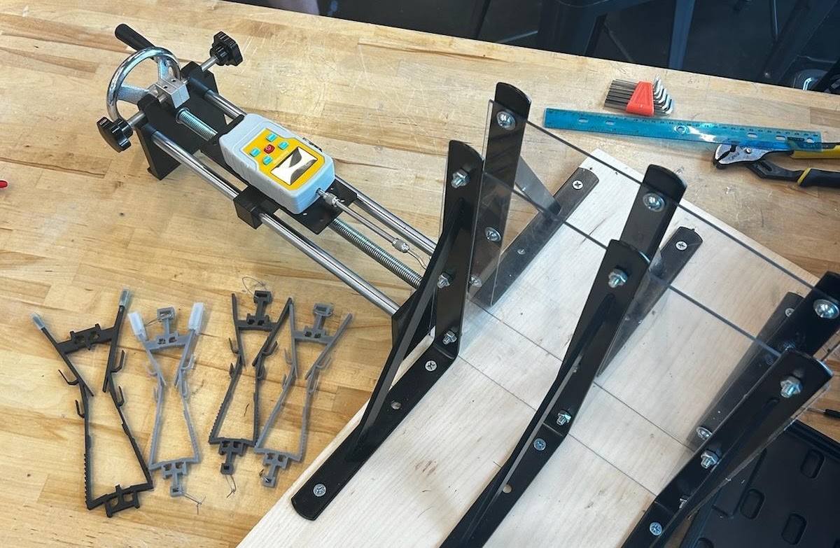
3D-printed legs in a hand-cranked force-gauge rig.
The 3D-printed legs were squeezed into a testing rig with rubber feet attached. The force gauge was manipulated via a hand crank on a sliding platform to horizontally move the specimen along the glass, capturing forward and backward motion forces.
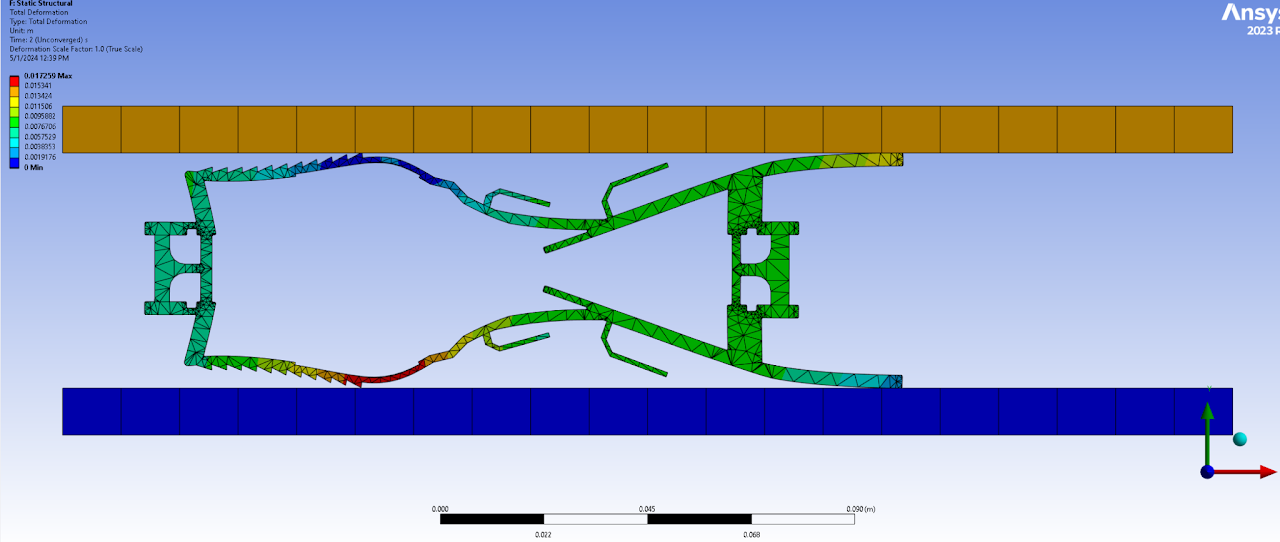
ANSYS simulations and physical prototype matching.
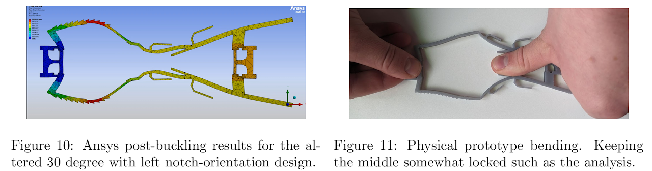
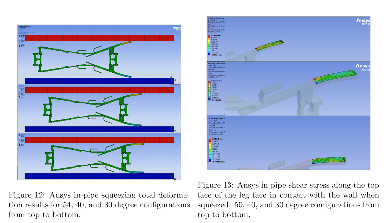
Contrary to initial expectations, inducing outward buckling proved challenging. A modified leg design was ideated with ANSYS. ANSYS in-pipe squeezing simulations were also performed to gain insight into predicting the anisotropic effect of different angled legs before casting any. A demo of the inward buckling and the ultimate success of the design is linked below.
Lab project on soft robotics. The leg is intentionally compliant: when it's loaded it buckles, but the geometry biases the buckling direction so the foot rotates predictably. FEA in ANSYS to design the shape, then a lot of silicone casting to test it. Worked surprisingly well in straight pipes; less well in elbows.
- ANSYS
- Silicone elastomer
- 3D printing